Buck LED driver not working (concept of floating and power ground)
Problem
A situation arrived to me while designing an AC to DC buck LED driver having floating and power grounds for isolation.
When I operated the proto, the response was not positive, so to see the waveforms and voltage levels I used the DSO. When I connected the ground pin of the DSO probe to the floating ground point of the circuit, the circuit operated.
Since during the previous testing the return path for the floating voltage was not there and as soon as I connected the DSO ground pin, a return path was established and the circuit operated.
Theory
Basically the concept of ground raised here. The floating and power grounds are two different terminologies. The power ground is connected to the negative reference but the floating ground, as the name suggests is not connected to any reference but floating and hence it was not getting any return path and the circuit was not complete so no operation.
The floating ground actually is not to be connected to any reference point, but the PCB design is to be made so that a parasitic capacitance is generated acting as an isolated return path for the circuit.
Solution
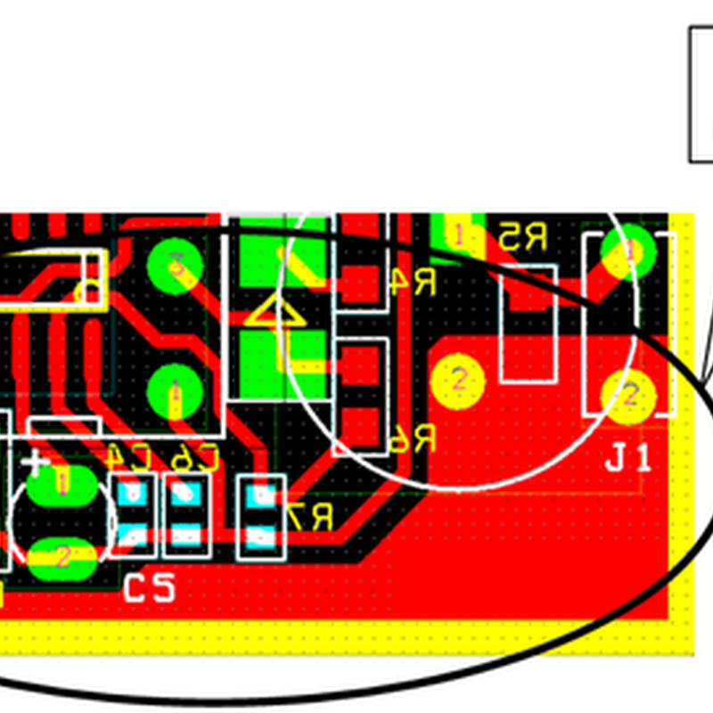
The PCB was redesigned with fewer and thinner tracks for floating ground and thicker tracks of power ground. Also both the tracks were placed close , this thicker and thinner combination generated a parasitic capacitance and a virtual connection between both the grounds. Just after this modification the desired output was achieved.
A situation arrived to me while designing an AC to DC buck LED driver having floating and power grounds for isolation.
When I operated the proto, the response was not positive, so to see the waveforms and voltage levels I used the DSO. When I connected the ground pin of the DSO probe to the floating ground point of the circuit, the circuit operated.
Since during the previous testing the return path for the floating voltage was not there and as soon as I connected the DSO ground pin, a return path was established and the circuit operated.
Theory
Basically the concept of ground raised here. The floating and power grounds are two different terminologies. The power ground is connected to the negative reference but the floating ground, as the name suggests is not connected to any reference but floating and hence it was not getting any return path and the circuit was not complete so no operation.
The floating ground actually is not to be connected to any reference point, but the PCB design is to be made so that a parasitic capacitance is generated acting as an isolated return path for the circuit.
Solution
The PCB was redesigned with fewer and thinner tracks for floating ground and thicker tracks of power ground. Also both the tracks were placed close , this thicker and thinner combination generated a parasitic capacitance and a virtual connection between both the grounds. Just after this modification the desired output was achieved.
 |


कोई टिप्पणी नहीं